2025-01-19

Displaying a dashboard with a Raspberry Pi

I now have a few old monitors I have hooked up to Raspberry Pi devices, which show custom full-screen web pages and live CCTV feeds. If there is a power outage, the dashboards restore themselves when the power returns just as they were before, without any manual steps required. I thought I would document the process in case anyone else is trying to achieve something similar.
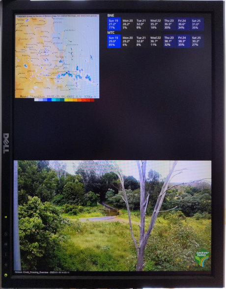
A dashboard on a portrait monitor showing weather radar, rain forecast and a static image from a municipal flood camera, refreshing once an hour or immediately if the images are clicked.
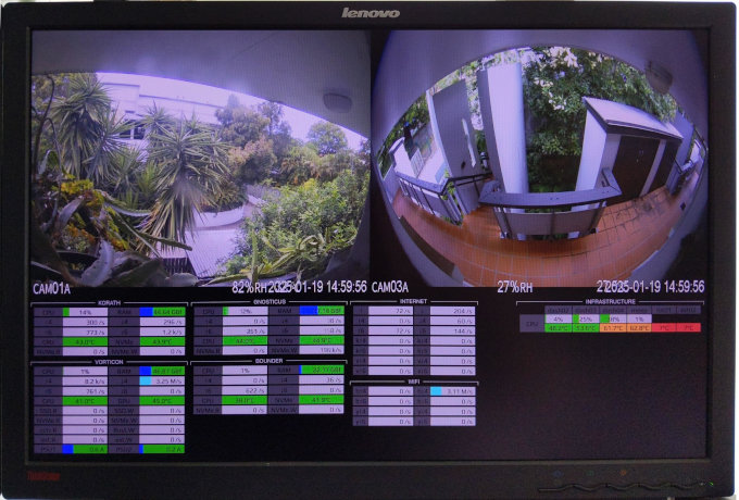
A landscape dashboard showing two live feeds from IP cameras, and a web page with live data from other devices on the network, such as CPU and memory use, IPv4/6 upload/download speeds, WiFi utilisation, etc.
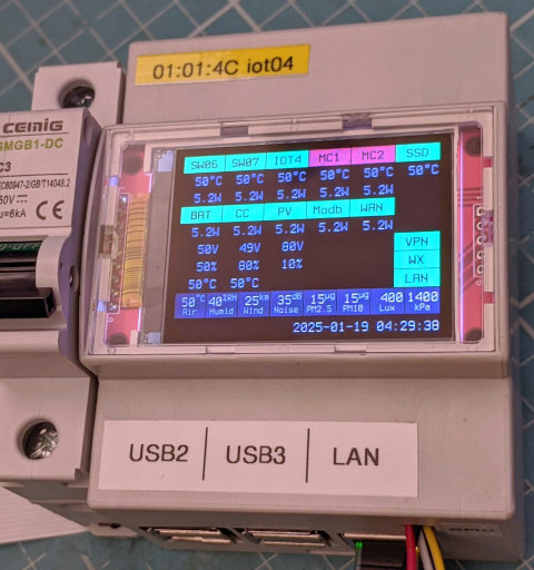
A dashboard on a Raspberry Pi 4, in a DIN-mounted case with an LCD hot-glued inside (a 2.2" ILI9341 connected via SPI).

The dashboards work by configuring the Pi to automatically log in as a "kiosk" user, start X11, then run the Chromium browser full-screen in kiosk mode. Kiosk mode limits many browser functions including hiding tabs and the address bar so it is perfect for this use case.

Firefox can also be used, however its kiosk mode is less refined. I found that when my Internet connection dropped out, Firefox would display a bunch of error messages about being unable to verify the security of its addons. Chromium however, continues to display a local HTML file even if there is no Internet connection, so it is more robust for this purpose.

This procedure is using Arch Linux ARM on Raspberry Pi devices, however it should work on any modern distribution that uses systemd, and with any other device capable of running Linux and X11. I am skipping the steps required to install various software packages as this varies considerably between distributions. You will need to work out yourself which packages to install, however X11, and optionally Unclutter, Chromium, Barrier and FFmpeg are all that is required. I am also skipping the X11 config. In my case it worked out of the box, however your device may require additional steps.

This procedure also assumes you have a web page or IP camera you wish to display. Creating your own HTML dashboard or configuring an IP camera is beyond the scope of this article.

The instructions here are suitable for multiple devices booting over the network and sharing a single filesystem. The scripts contain conditional blocks to ensure different devices show different content, even though they are all configured the same. Network booting is not required however, and this process works equally well when booting from local storage.

Make X11 start on boot

  1. Create a new user called kiosk. The web browser will run as this user, so it only needs limited access. Create a home directory for this user and assign it the proper permissions.

    useradd -g users kiosk
    mkdir /home/kiosk
    chown kiosk:users /home/kiosk
    
  2. When you su kiosk to become the kiosk user, you will find many commands do not work. This is because some environment variables are set to your login user and not the kiosk user, so they have to be updated. If you are using the Bash shell, you can do this automatically:

    # /home/kiosk/.bashrc
    
    export XDG_RUNTIME_DIR=/run/user/$UID
    export DBUS_SESSION_BUS_ADDRESS="unix:path=$XDG_RUNTIME_DIR/bus"
    export DISPLAY=:0
    

    Now after running su kiosk things like systemctl --user restart chromium.service will work as expected. If you try running systemctl --user status and get an error, run echo $XDG_RUNTIME_DIR to confirm the environment variables really were updated, and the UID is correct for the kiosk user.

  3. Make this user log in automatically when the system boots. This can be done by creating a systemd override. You can do this via the CLI, or just create /etc/systemd/system/getty@tty1.service.d/override.conf with this content:

    [Service]
    ExecStart=
    ExecStart=-/usr/bin/agetty --autologin kiosk --noclear %I $TERM
    
    # Start immediately, don't wait for boot to finish
    Type=Simple
    
  4. Make X11 start as soon as the kiosk user is logged in. I did this by creating /home/kiosk/.bash_login with the following content:

    # Start Xorg, run .xinitrc and exit when .xinitrc finishes.
    exec /usr/bin/xinit /usr/bin/sh ~/.xinitrc -- -keeptty -sharevts 2>&1 | tee .local/share/xorg/xinit.log
    

    If you run into problems getting X11 started, you can look at /home/kiosk/.local/share/xorg/xinit.log for error messages. Alternatively, SSH into the device, then as root run xinit -- -keeptty -sharevts to try to start X11. If it fails, you will see the reason in your terminal.

  5. When X11 starts it will now run .xinitrc in the kiosk user's home directory, so we can put commands in there to run once X is going.

    # Make $DISPLAY available to systemd user units
    /etc/X11/xinit/xinitrc.d/50-systemd-user.sh
    
    # If this machine is called "dash02" then rotate the screen by 90 degrees as
    # the monitor is in portrait orientation.
    if [ "$HOSTNAME" == "dash02" ]; then
            xrandr --output HDMI-1 --rotate left
    fi
    
    # Always keep the screen on
    xset -dpms
    xset s off
    xset s noblank
    
    # Make sure the temporary profile folder is available
    mkdir /tmp/chromium-kiosk
    
    # Hide the mouse cursor if it hasn't moved for some seconds.
    unclutter -timeout 10
    
    # Keep the session open
    exec cat
    
    # NOTE: Barrier and other things are launched in /etc/systemd/user/
    
    Omit any part of this that is not relevant to your needs. The reason for the condition that checks for the "dash02" hostname is because I share the same configuration files amongst all dashboard devices, so this allows device-specific configuration without needing to worry about getting the right version of each file onto the correct device. I can just deploy the same files to all devices to keep it simple (in my case many of them boot over the network from the same shared filesystem).

Start graphical apps with X11

  1. Create a systemd user service for Chromium. This allows systemd to handle automatic restarts if the process crashes.
    # /etc/systemd/user/chromium.service
    [Unit]
    Description=Run Chromium in Kiosk mode
    
    [Service]
    ExecStart=/etc/systemd/user/chromium.sh %l
    
    Restart=always
    RestartSec=2
    
    # Make it very likely to be killed in low memory situations.  This is
    # because a memory leak in a web page is going to be the most likely
    # reason for running out of memory, so terminating the browser first
    # (where systemd will immediately restart it) is probably the most
    # likely way to recover from that situation.
    OOMScoreAdjust=800
    
    [Install]
    WantedBy=default.target
    
    # /etc/systemd/user/chromium.sh
    #!/bin/sh
    
    HOSTNAME="$1"
    
    # Make sure X is running
    xrdb -query dummy || exit 1
    
    URL="file:///srv/web/index.html?hostname=$HOSTNAME"
    case "$HOSTNAME" in
      dash01)
        POS="1920,750"
        SIZE="1920,450"
      ;;
      dash02)
        POS="0,0"
        SIZE="1200,1600"
      ;;
      dash03)
        # Don't run at all
        exec cat
      ;;
      iot04)
        POS="0,0"
        SIZE="320,240"
      ;;
      *)
        echo "Host '$HOSTNAME' not implemented."
        exit 1
      ;;
    esac
    
    exec /usr/bin/chromium \
      --no-sandbox \
      --window-position="$POS" \
      --window-size="$SIZE" \
      --ignore-gpu-blocklist \
      --enable-gpu-rasterisation \
      --enable-accelerated-video-decode \
      --no-v8-unntrusted-code-mitigations \
      --no-pings \
      --no-recovery-component \
      --no-first-run \
      --noerrdialogs \
      --start-fullscreen \
      --start-maximized \
      --disable-notifications \
      --disable-infobars \
      --disable-translate \
      --disable-features=Translate \
      --kiosk \
      --incognito \
      "$URL"
    

    Adjust chromium.sh as needed for your desired screen size and position. In this example dash01 is on the lower half of the second screen of a dual-monitor dashboard (to make room for a live CCTV image on the upper half of the display), dash02 is on a 1600x1200 monitor in portrait mode (so 1200x1600), and dash03 does not run Chromium at all, but since all these files are identical amongst all devices we need to pretend the script started successfully, otherwise systemd will keep trying to restart it over and over burning CPU cycles.

    Note the URL I am loading on all dashboards is the local file /srv/web/index.html. Change this to suit your needs. In my case that file contains Javascript that examines the ?hostname= parameter and creates DOM elements on the page depending on the host. You may wish to do things differently, such as setting URL= inside the case block, to display a different URL depending on the hostname.

  2. I use Barrier for the dashboards near me, so I can move my mouse over to them to click buttons on them:

    # /etc/systemd/user/barrierc.service
    [Unit]
    Description=Run Barrier keyboard/mouse sharing client
    
    [Service]
    ExecStart=barrierc --no-daemon --disable-crypto --name %H barrier-server.example.com
    Restart=always
    RestartSec=2
    
    [Install]
    WantedBy=default.target
    
  3. These new systemd user services need to be activated. You can do this as the kiosk user with systemctl --user enable chromium.service and the same for Barrier if you wish. If you don't want to use Barrier, omit the activation here and it will not run, even if the above barrierc.service file is present.

Display live video from IP cameras

  1. I use ffmpeg to display a live multicast video feed from IP cameras (skip this step if you don't wish to do this). This feed can be sent from the camera on another Pi, or from a Dahua IP camera. Other IP cameras (e.g. Hikvision) do not properly implement multicast so you will need to work out how to receive a video stream yourself, by modifying the ffmpeg command in the script below.

    # /etc/systemd/user/picam-view.sh
    #!/bin/sh
    
    CAM="$1"
    VF=""
    PARAMS=""
    ACCEL=none
    
    # Use -v to show ffmpeg messages and commands
    if [ "$2" == "-v" ]; then
      VERBOSE="-v"
      set -x
    else
      PARAMS="$PARAMS -loglevel repeat+level+fatal"
    fi
    
    if [ -e /dev/video12 ]; then
      # Use Raspberry Pi hardware-accelerated decoder
      ACCEL=pi
      echo "Using Pi acceleration"
    elif [ -e /dev/video19 ]; then
      # Raspberry Pi 5 - no acceleration
      ACCEL=none
      echo "Using Pi acceleration"
    elif [ -e /dev/dri/renderD128 ]; then
      # Use Intel hardware-accelerated decoder
      ACCEL=vaapi
      echo "Using VAAPI acceleration"
    fi
    
    # Set window location
    case "$HOSTNAME" in
      # Specific settings for each dashboard.
      dash01)
        case "$CAM" in
          # Camera-specific settings for this dashboard.
    
          # This one is full screen (a 1920x1200 window starting at 0,0)
          # but the source image is cropped with FFmpeg's "crop" filter.
          cam02a-hd) VW=1920; VH=1200;  X=0;  Y=0; WIDTH=$[1920-$X]; HEIGHT=$[$VH*$WIDTH/$VW]; VF="crop=1583:$[1080-90]:0:90," ;;
    
          # These ones are just scaled and positioned side by side, as
          # shown in the landscape example at the top of this post.
          cam01a*) VW=1280; VH=996;  X=1920; Y=0; WIDTH=960;  HEIGHT=$[$VH*$WIDTH/$VW] ;;
          cam03a*) VW=1280; VH=996;  X=$[1920+960]; Y=0; WIDTH=960;  HEIGHT=$[$VH*$WIDTH/$VW] ;;
        esac
      ;;
      dash0[34])
        # More examples for the dash03 and dash04 devices.
        case "$CAM" in
          cam02a-hd) VW=1920; VH=1200;  X=0;  Y=0; WIDTH=$[1920-$X]; HEIGHT=$[$VH*$WIDTH/$VW]; VF="crop=1583:$[1080-90]:0:90," ;;
          cam02a-4k) VW=1920; VH=1200;  X=0;  Y=0; WIDTH=$[1920-$X]; HEIGHT=$[$VH*$WIDTH/$VW]; ;;
          cam01a*) VW=1280; VH=996;  X=0; Y=0; WIDTH=960;  HEIGHT=$[$VH*$WIDTH/$VW] ;;
          cam03a*) VW=1280; VH=996;  X=960; Y=0; WIDTH=960;  HEIGHT=$[$VH*$WIDTH/$VW] ;;
        esac
      ;;
    esac
    
    # Add hardware acceleration parameters based on detection above.
    case "$ACCEL" in
      vaapi)
        PARAMS="$PARAMS -hwaccel vaapi -hwaccel_output_format vaapi"
      ;;
      pi)
        PARAMS="$PARAMS -codec:v h264_v4l2m2m"
      ;;
    esac
    
    # Add video source
    # Example 1: Use sed to convert "cam12" into IPv6 "[ff08:1500::ca12]"
    #IP=`echo "[ff08:1500::$1]" | sed "s/cam/ca/"`
    # Example 2: User sed to convert "cam04" into IPv4 "239.0.0.4"
    #IP=`echo "239.0.0.$1" | sed "s/cam0*//"`
    # Example 3: Use the camera name with a fixed domain, with the IP loaded from /etc/hosts or via DNS.
    MC_SOURCE="$CAM.mc.camera.example.com"
    # Regardless of what we picked above, use UDP streaming on port 5004.  Change this if you're not using multicast streaming on port 5004.
    PARAMS="$PARAMS -fflags +nobuffer -i udp://$MC_SOURCE:5004"
    
    # Hardware scaling if available.
    if [ $ACCEL == vaapi ]; then
      VF="${VF}scale_vaapi=w=$WIDTH:h=$HEIGHT,hwdownload,format=yuv420p,"
    fi
    
    # Try to display frames as quickly as possible to avoid lag.
    VF="${VF}setpts=N/30/TB"
    
    PARAMS="$PARAMS -aspect $WIDTH:$HEIGHT -vf $VF -f xv -window_x $X -window_y $Y -window_size ${WIDTH}x${HEIGHT} $CAM"
    
    # Run ffmpeg to display the video feed.
    echo /usr/bin/ffmpeg $PARAMS
    /usr/bin/ffmpeg $PARAMS
    
  2. This script needs to be launched with another systemd user service. This is because ffmpeg can easily crash due to corrupted video or running out of memory, so having systemd restart it when that happens ensures that the video feed is never lost for too long.

    # /etc/systemd/user/picam-view@.service
    [Unit]
    Description=Live feed from IP camera
    
    [Service]
    # Make sure X is running
    ExecStartPre=xrdb -query dummy
    
    # Remember to escape dashes: systemctl --user start picam-view@cam02a\\x2dhd
    ExecStart=/etc/systemd/user/picam-view.sh %I
    Restart=always
    RestartSec=2
    
    # Kill and restart if using too much memory
    #MemoryMax=96M  # too small for cam02a-4k
    MemoryMax=256M
    
    [Install]
    WantedBy=default.target
    
  3. Enable this service (as the kiosk user, see below) with systemctl --user enable picam-view\@cam01, assuming your camera is called cam01. If X11 is running, you can test your options (like screen positioning, cropping, etc.) with systemctl --user restart picam-view\@cam01. You can keep modifying the script and restarting until you're happy with the outcome.

2024-06-08

Replacing exit rollers on a Fujitsu ScanSnap iX500

I recently went to scan a document with my ScanSnap iX500 scanner, and the surface of the paper ripped off and wrapped itself around the exit rollers. It turned out that the exit rollers had turned soft and sticky, similar to the consistency of blu-tack.

The factory exit rollers have turned into sticky mush.

These rollers are not considered a user-replaceable part, as they are supposed to last the life of the scanner. If they need replacing you are supposed to send it back to Fujitsu, however they won't repair devices that have reached end-of-life, as this model of scanner has.

Luckily there are replacement exit rollers for sale on eBay, however the process of installing them is somewhat involved so I have documented the procedure I used here, in case it is of any help to someone else in the future.

Procedure

First, undo the two screws on the bottom of the unit to loosen the outer plastic case. Next, open the scanner (as if you were clearing a paper jam) and lift up the plastic plate covering the grey pick roller. Remove this plate entirely.

A screw needs to be removed for later, and two clips released to get the back cover off.

Once the plate has been removed it will look like the above image. Undo the single screw for later, and release the two clips holding the back case on. With these removed, the back plastic case should lift right off.

Back case removed. All the connectors have to be removed in order to take the controller board out.

With the case removed, the main controller board is revealed. Next, remove both sides of the scanner. These can be pulled/wiggled out. There are a number of clips that must unhook, and pulling while rotating the sides back and forth caused them all to release for me, and the side panels came off cleanly.

Lower exit rollers

With the sides off, the plastic housing covering the lower exit rollers can be removed. This provides access to the lower rollers.

The rollers are held in with bushings, which need to be rotated 90 degrees in order to unlock from the plastic. A small clip prevents them from being rotated, so the clip must be held back while the bushing is rotated. Do this for both bushings on either side of the exit roller rod.

The bushing needs to be rotated 90 degrees to release it from the plastic case.

Once this is done the exit roller will move freely. In order to remove it, the black gear on one end of the rod will need to be removed. There is a clip holding the gear in place, and once it has been released, the gear will slide off the rod. I found using a pair of pliers helpful for this, however make sure you are very gentle as you don't want to snap the clip, otherwise the gear won't lock back onto the rod later.

The rod holding the exit rollers can now move freely.
Using some pliers can help push the gear off the end of the rod. Be sure to release the locking clip first so as not to snap it.

Once the gear is removed the exit roller rod can be removed from the scanner and the old mushy rollers removed. Remember to remove the black foam spacers first, so they can be reused later.

I found that using a stanley knife (box cutter) to scrape down the metal rod a few millimetres at a time to be quite successful, working my way 360 degrees around the rod, inching down a little each time. Eventually the old rollers squashed into a donut shape but came off without leaving any residue on the rod.

Push the replacement rollers in, reinstall the foam spacers, the follow the same steps in reverse to get the exit roller rod back in place.

I found the replacement rollers quite tight, and used an old piece of wood to push the rollers down the rod. The piece of wood had a hole in it that was large enough for the rod to pass through, but too small for the roller itself to pass through.

Do not bother trying to get the belt back onto the black gear, as the whole belt has to be removed to replace the upper exit roller next.

The new exit rollers reinstalled.

Upper exit rollers

To remove the upper exit rollers, the whole control board and motor needs to be removed.

Unplug all the connectors and undo three screws (one on the left that screws into plastic, and two in the middle - one that screws into metal, and another that screws into plastic and has a grounding wire attached.

This should allow the control board to be completely removed.

Next, unplug the white connector and use the clips shown below to remove the plastic backing plate.

After the main control board has been removed, unplug the white connector and use the clips to release the plastic backing plate.

At this point the motor must also be removed in order to access the upper exit roller rod. This means unscrewing two screws on the side of the unit. One has an arrow molded into the plastic, and the other is for the belt tensioner. Both these screws must be undone.

Now the motor can be slid out, noting that there is a clip that may need to be pulled back to fully release it.

At this point the upper exit rollers should be accessible. As before, two bushings will need to be released by rotating them 90 degrees (after unclipping them), and this time there are gears on both ends of the rod that will need to be removed.

Remove the white gear to release one side of the upper exit roller rod.

Remove the white gear to free one end of the rod, and note (or take a photo) of the pattern on that end of the metal rod. It is different to the other end, so it is important to remember which end goes where.

Remove the upper exit roller's bushings as well.

Remove the black gear from the other end of the rod, and the rod can slide out with the old exit rollers attached. As before, clean them off and insert the replacement rollers.

Follow the procedure in reverse to get the exit roller rod back in place and the bushings locked. You may need to press down on the rod in order to get the bushings to rotate into place, as the new exit rollers now press harder on their opposite number, causing the rod to sit up a little higher than before.

Reassemble everything, and when reinstalling the belt tensioner, set the tension to firm but not too tight.

Both upper and lower exit rollers have now been replaced.

2018-11-05

Disassembling and cleaning an LTO tape drive head

I recently obtained a faulty LTO5 tape drive with a sticky head. I was able to successfully repair it by just giving it a good clean, and the drive is now fully functional again. To help anyone who might come across the same problem in the future, I took some photos of the process. Although this was an LTO5 drive, the procedure is likely to be very similar for other generations of LTO drives as well. However this was a HP drive, so the procedure will likely only apply to other drives manufactured by HP.

Symptoms

When inserting a tape, the drive normally makes one or two knocking noises. This is the drive making sure the head can move through its full range of motion. This particular drive was making a number of knocking sounds (around 10) and then immediately ejecting the tape. Running HP Tape Tools diagnostics on the drive reported that the drive "may have problems loading a tape" and the Drive Assessment Test failed early with an error about the head not moving the expected distance.

Inserting a cleaning tape resulted in the drive winding it in quite some distance and then rebooting (all LEDs light up). The drive then went into 'power on with tape loaded' mode, very slowly rewinding the tape over many minutes and then ejecting it. The drive logs reported the drive being power cycled while a tape was loaded, even though power was not lost to the drive. Apparently there is a bug in the firmware and inserting a cleaning tape when the head cannot move properly causes the firmware to crash and reboot.

Disassembling the drive and gently moving the head with a pair of tweezers showed that the head did not move freely and there was some very slight friction at two points along its journey. Inserting a tape with the drive's cover removed (so the head was visible) revealed that the head could not lift all the way up under its own power, and the repeated knocking sound was the head trying a number of times to unsuccessfully move. Using tweezers to assist the head resulted in the drive loading a tape, and the head appeared to move perfectly fine after this point. However HP Tape Tools revealed high error rates (poor write speeds) and the drive had problems finding the start of the tape.

Solution

After disassembling the drive, it turned out that there was a tiny build up of some gunk (dust?) on the shaft that the head slides up and down on. There is no way to get access to clean this shaft unless the whole head assembly is removed from the drive and disassembled, however this is actually a relatively straightforward task, and isn't overly fiddly. With only a little care, the drive heads remain aligned so the risk of damaging the drive is minimal. (Of course the old saying applies: YMMV, do this at your own risk, etc, etc.)

Drive disassembly

To disassemble the drive you will need a T8 torx bit to remove the screws on the top of the drive, and a T4 torx bit to disassemble the head itself. You'll also need a pair of needle-nose pliers or similar in order to undo two nuts to release the head assembly.

First remove the four screws that hold the top of the drive's metal case, and cut the various stickers. Lift the top off gently so the thermal pads aren't damaged.

Once the lid is off, the main PCB is exposed. This needs to be completely disconnected. Remove all the cables connecting to this board, as shown in the images below.

The flat ribbon cables need to be released differently. The ribbon cables with a blue end are released by lifting up the black part of the socket from the back, while the other cable is released by lifting up the black part from the front. I used tweezers to gently lift it. The following two photos show the two variants of the connectors before and after release.

Small connectors when secured.
Small connectors after release.

Disconnect all the cables on the board.

Cables to disconnect, noting the two white clips at the bottom left.

The board must be lifted up slightly (and wiggled out of the way of the white plastic clips) in order to access the last two connectors. The flat ribbon cable is gently pulled out, while the white connector for the ejection motor requires a little more force, but be careful not to damage the connector. Wiggle it quite a bit as you are pulling it to release it.

The board must be lifted up to remove these last two connectors.

Once the main PCB has been removed, locate the head assembly towards the rear of the drive. There are two shafts that secure the head assembly into the drive, and both of them have a spring and a nut on them so are easily identified. Unscrew the nut and remove the spring. This releases the head assembly but do not lift it out yet as more cables need to be detached first.

Be careful to leave the other grub screws untouched in the corners of the head assembly base, as these are used to align the head. If they are moved then the head will not read or write data at the correct angle and the drive will need to be professionally recalibrated before it will work again.

One of the two securing shafts for the head assembly.
Shaft with nut and spring removed.

Now the data cables for the head itself need to be removed. On the side of the drive there is a hole with a black plastic catch sitting in it. Poke this in a little to release the plastic bracket holding the data cable in place, which can then be lifted up completely clear of the drive.

Once released, lift here.
The two parts that should lift out, and the hole that needs to be poked to release the black plastic bracket.

Once the head's data cables are free, the head assembly can be completely lifted out of the drive. Be careful not to touch the head itself.

Head assembly removed from drive.

Set the drive aside as we are now focusing on just the head assembly. The whole thing needs to be disassembled and it comes apart into five pieces: the base, the head, the housing and two small metal cylinders.

First, turn the assembly upside down and undo the two screws that hold the housing in place. Leave the third screw in place.

Screws to remove from the underside of the head assembly.

Next, pull the housing away from the base, if possible leaving the head on the base. If the head comes off it's fine, it can just become stuck if it moves around too freely during the procedure. Note that the head is attached to the base by a thin ribbon cable with a white connector. This will need to be removed at some point before the head is lifted off the base, however the housing sometimes gets in the way. Try to remove it if you can, otherwise be sure that the head does not lift off the base when you remove the housing.

There are strong magnets in the housing, so it will require some force to move and you may need to lever it at first with a screwdriver or similar. Be very careful not to damage the head itself during this process.

As you lift the housing off, two small metal cylinders will fall out and stick to the magnets. Just ignore these, but at this point you cannot go back as the cylinders now prevent the housing from being pushed back in place.

The metal cylinders that have come loose from their holes.

I drew a black dot on one side of the cylinders so I could be sure I was inserting them back in the same way later, but they turned out not to be magnetic so this may not matter. However you may like me wish to err on the side of caution! You will need pliers or similar to remove the cylinders as the magnets they are stuck against are quite strong. Set the cylinders aside as they are placed back in the housing later after reassembly, from the top instead.

The head can now be lifted out of the base if it did not come out already, after carefully disconnecting the thin cable if you haven't already.

The head after removal from the base. There was some gunk inside the coil shown by the arrow, which was cleaned off with a cotton bud (Q-tip).
The base of the head assembly. There was a buildup of something where the arrow is pointing, which was also cleaned off with a dry cotton bud.

Simply rubbing the surfaces with a dry cotton bud did the job in my case, however when running it along the thick shaft on the base of the head assembly (see arrow in previous pic) there was noticeable friction in exactly the same pattern as the head exhibited earlier. Scrubbing this until it was mostly smooth did the trick, as reassembling the head immediately revealed that there was no further friction and the head could slide smoothly along the shaft once again.

To put the head assembly back together, place the head onto the base and gently push the housing over the top, leaving the two small metal cylinders aside for later. Be sure the housing fits snugly and there are no gaps between the housing and the base, as this is easy to have happen because of the strong magnets. Screw the housing back to the base and confirm that the head still slides smoothly. Don't forget to reconnect the small ribbon cable with the white connector.

Peel the cable and sponge off the top of the head housing to reveal the holes where the cylinders go. Pop both cylinders back in and press down the cable and sponge again.

The holes where the metal cylinders are returned to.

Follow the rest of the disassembly instructions in reverse, remembering to connect all the cables on the PCB before switching the drive back on again.

Hopefully you have the same success that I did!

2016-12-28

Using a Seagate rackmount NAS with Linux

Having recently obtained a Seagate Business NAS for use in my home network, I came across a few issues setting it up which I will explain here in case it helps anyone else one day.

Seagate 4-bay rackmount NAS. No, it doesn't have a short name.

Firstly, for those who haven't used these devices (codename "charger"), they are very nicely designed. They are essentially low-power PCs (Intel Atom CPUs), running a customised (but standard) PC BIOS, and the power supply even uses a standard ATX connector. The BIOS has limited configuration options, but is programmed to boot from a USB stick first, then each drive one by one. The USB stick is used to install the operating system, which is then mirrored across all disks via RAID1 so as long as one disk is present, the OS and all config options will be present.

Despite the device using a low-power CPU, it is easily able to max out the gigabit network connection without jumbo frames, using only around 30% CPU (for RAID0 - the CPU use may increase if RAID5/6 is used instead.) Jumbo frames can be enabled - the MTU can be set to 1500, or 2000 to 9000 in increments of 1000.

Installing NASOS

My device unfortunately didn't come with a NASOS install key thanks to it being second hand, so I had to create one myself. Sadly since the creation program is Windows only, I had to improvise.

Without going into too much detail (this is for experienced Linux users after all), here are the steps to create your own NASOS installation USB stick under Linux.

  1. Figure out where the target USB stick is. This assumes the USB stick is /dev/sdd, so change as needed.
  2. Partition the USB stick with a single FAT32 entry, making sure it is active so it can be booted.
    1. Run fdisk /dev/sdd
    2. Make a single primary partition, type "c" (FAT32 LBA)
    3. Make the partition active ("a")
  3. Put a FAT32 filesystem on the new partition:
    mkfs.vfat /dev/sdd1
  4. Make the USB stick bootable with Syslinux:
    syslinux --install /dev/sdd1
    
  5. Copy the NAS OS install onto the USB stick:
    mkdir /mnt/nasos
    mount /dev/sdd1 /mnt/nasos
    cd /mnt/nasos
    tar xvf /path/to/windows/install/Data/charger-rescue_x.x.x.x_usb.tar
    
  6. Edit /mnt/nasos/syslinux.cfg to set the USB partition ID.
    • Replace %UUID% with the UUID of the /dev/sdd1 partition
    • Run ls /dev/disk/by-uuid and look for /dev/sdd1 to find the UUID
  7. Clean up:
    cd /
    umount /mnt/nasos
    rmdir /mnt/nasos
    

You should now have a USB stick that the NAS will boot to install the OS.

Connecting to the NAS under Linux

There are plenty of connectivity options however the two I will focus on are NFS and CIFS. Both of these have a number of drawbacks in the way they are implemented on this device:

NFS:

  • When NFS is enabled, all shares become public
  • No IP-address restrictions
  • No UID/GID mapping
  • Symlinks cause problems when the share is viewed via CIFS

CIFS:

  • Can't create symlinks

Since CIFS only has one drawback, the easiest solution appears to be to use CIFS and get symlinks working. This will allow NAS shares to function much more like local storage.

Since the NAS is a standard Linux box, with CIFS services provided by Samba, this should be an easy fix. The easiest option would appear to be to mount the shares with the sfu option, which enables Microsoft's "Services for UNIX". Unfortunately while this mounts the share without any problems, symlinks still cannot be created for some reason, even though this is supposed to be possible.

To properly fix this problem, Samba needs to be configured to enable UNIX Extensions. This is disabled by default, and there is no option to enable it, so this is where things get interesting.

In order to enable UNIX Extensions, the NASOS needs to be modified. By default the Samba option for UNIX Extensions is hard-coded as off, so the code that produces smb.conf needs to be modified to turn it back on. Luckily, NASOS is relatively open so this is actually quite straightforward.

  1. Log in to the NAS via SSH, with one of the accounts in the Administrators group.
  2. Gain root access with sudo su and re-enter the account's password.
  3. Enable write access to the OS partition:
    mount / -o remount,rw
  4. Edit the file /usr/lib/python2.7/site-packages/unicorn/sharing/smb.py
    • Tip: vi is the only editor available. If you aren't familiar with it, copy the file into one of the folders in /shares/ and then edit it on another machine.
  5. Search for unix extensions and change no to yes
  6. Recreate the Python cache file:
    cd /usr/lib/python2.7/site-packages/unicorn/sharing/
    rm smb.pyc
    python
    import smb
    quit()
    
  7. Return the root partition to read-only:
    mount / -o remount,ro
  8. Reboot the NAS to pick up the change (restarting Samba isn't enough as the Python code we just modified needs to be restarted too.)
    reboot

After the reboot, /etc/samba/smb.conf should have been recreated automatically and should now contain the line unix extensions = yes.

You can now mount the share and create functioning symlinks successfully! With UNIX Extensions, the NAS UID/GIDs will now become visible, so you will need to override these to avoid permission errors on the local machine.

Here are the options I use to mount the shares from a Linux client in /etc/fstab:

//nas/share  /mnt/share  cifs  credentials=/etc/samba/private/nas.conf,noacl,nosetuids,uid=1000,gid=100,forceuid,forcegid,mapchars,file_mode=0644,dir_mode=0755,noperm 0 0

The options are:

noacl
The NAS doesn't use ACLs so this just cleans up the appearance of the files so they don't all look like they have empty ACLs attached.
nosetuids
Don't set the owner/group on newly created files, leave it at whatever the server wants. This is the behaviour when UNIX Extensions are disabled, so we have to specifically disable it now we've turned UNIX Extensions on. You don't need this of course if you *want* to be able to have different owners and groups on the files in the shares, but it's a moot point because you connect to the share as a normal user so don't have access to change file owners anyway.
uid=1000
gid=100
This is the owner and group that the files should appear to be owned by on the local machine. Since we are using noperm these are ignored, so they are only here for cosmetic reasons. If you weren't using noperm, you could set this up so that only this user can access the local mount.
forceuid
forcegid
Use the uid= and gid= options even when the server supports UNIX Extensions.
mapchars
Map characters that are illegal on Windows (:, ?, etc.) to and from Unicode chars that look similar. This will allow you to store files on the share with these characters in the name, rather than getting an error instead.
file_mode=0644
dir_mode=0755
Permissions to show all files and folders as having. Again these are ignored due to noperm. Without UNIX Extensions these are the modes (permissions) all files will get, however they are ignored when UNIX Extensions are enabled. This causes us problems, as typically the modes returned from the server are world-writable, so the local mount point can't be locked down anyway. Hopefully one day soon a mount option will be added for CIFS to respect these two options, even when UNIX Extensions are active.
noperm
Ignore all permissions client-side and let the server handle everything. I only use this on some shares I want to share with non-Linux machines, so that the permissions will always be set by the server for maximum compatibility.

The reason for most of these options is because I want to maximise interoperability between multiple machines accessing the same share. I don't want to have Windows machines unable to access files because I forgot to change the owner when I created the file under Linux.

If you will only be accessing a particular share from one machine, or all your Linux machines have the same UIDs and GIDs assigned, then you can consider leaving out most of these permission-disabling options to make the shares behave as closely as possible to how a local filesystem would act. However be aware that this alone won't be enough and you'll need to further modify the code that produces smb.conf. This is because the share is mounted as a non-root user on the server side, so that user will need to be mapped to root in order to allow a file's UID/GID to be changed. I'm not going to cover this because it gets a bit more complicated and it's not something I need to do - I am fine with anyone who has access to a particular share being able to access everything on it.

Background - Why use a NAS device at home?

In my endless quest to remove clutter from my computing area, I switched some time back to a rackmount PC. This worked very well to hide the PC away, however hiding the wiring as well meant that I needed five metre cables for most things.

Five metres is about the limit of many types of cables, with the most problematic being USB and DisplayPort. I found that passive 5m USB 2.0 cables would work for a few months then stop functioning, and active USB 2.0 extension cables would occasionally malfunction and the repeater end would become extremely hot. Fixing the problem required digging around in the back of the rack to unplug and reconnect the cable which was rather tedious. Active USB 3.0 cables were better, but again, some would work with some devices and some would not. Same story with DisplayPort, especially for 4K@60Hz.

Eventually I found a combination of cables that mostly work, most of the time, but the situation still isn't really ideal.

So to avoid this, I have decided to try out Intel NUC devices. With the latest models at last offering quad core CPUs (very useful for parallel code compilation), these are now as powerful as a real (non-gaming) PC, and they can be mounted on the back of a monitor allowing the use of very short cables. The only drawback is the limited potential disk space due to the small form factor, so by moving everything over to an Ethernet-connected NAS, I can enjoy as much disk space as I need without it taking up any space near my computing desk

2016-01-09

Using SIMMs as SIPPs

Before the IBM AT and the 80286 were introduced, the RAM in most PC clones was comprised of a number of individual ICs plugged into sockets on the motherboard. Since the 8086 could only address up to 1MB of memory, this arrangement worked well.

However when the 80286 came onto the scene, it could make use of up to 16MB of memory. As memory was still very expensive, and motherboard manufacturers didn't want to populate their boards with thousands of IC sockets, a new standard was needed to allow memory to be expanded as needed by the end-user.

One of the first of these was the Single Inline Pin Package (SIPP), which had the same 2.54mm pin spacing as one half of an IC, allowing existing IC sockets to be used as receptacles for the new type of memory.

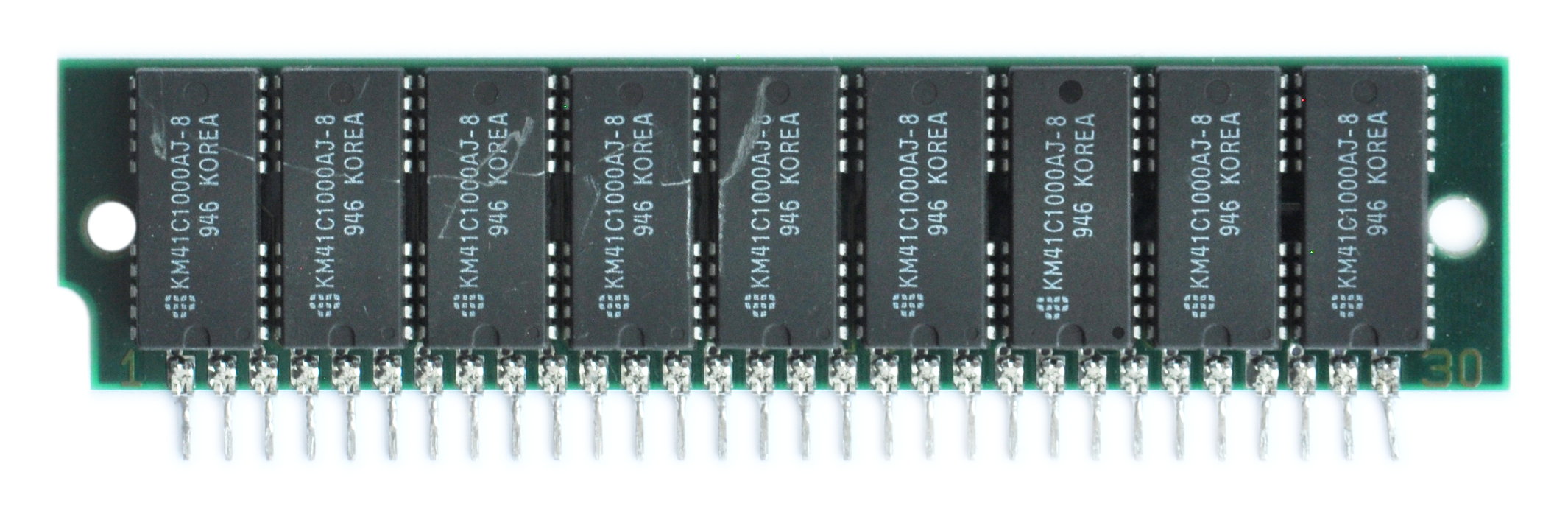
A 1MB SIPP module

The new SIPPs proved to be somewhat troublesome with their easily bent pins, and before long were replaced with SIMMs. SIMMs had no pins at all and used edge-connectors on the PCB instead, making them much more durable.

Since SIPPs were so short-lived, they are not readily available in the vintage PC marketplace. This is a problem for the retro PC enthusiast wanting to add additional memory to a motherboard with only SIPP sockets. When looking at my own "M209" 286 clone motherboard, the two spare SIPP sockets were crying out to be populated!

Two empty SIPP sockets, waiting to be used

Luckily, the two standards are electrically compatible, so all it takes to make use of SIMMs is some way of making the mechanical connection. There are a few options for this:

  • Desolder the SIPP socket and replace it with a SIMM socket.
  • Solder pins onto a SIMM, turning it into a SIPP.
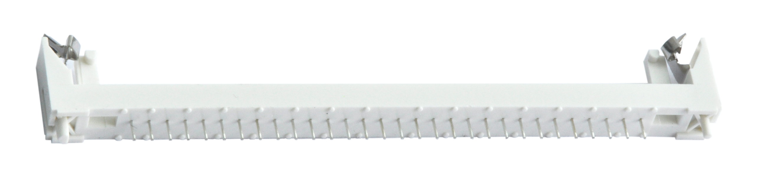
  • Use an adapter to convert the SIPP socket into a SIMM socket.

The first option involves removing the SIPP socket and replacing it with a SIMM socket. While this is a very good solution and only involves a little soldering, it is a rather permanent change and removes the novelty of having a somewhat rare motherboard that uses SIPPs. For me this was tempting, especially as my motherboard was designed to host either socket type - it already had SIMM mounting holes - but then there would have been one less unique thing about this motherboard so I decided against it.

The second option involves finding 30 bare IC pins, and soldering them onto a SIMM. This is not that unusual, as many later SIPPs were actually SIMMs with pins soldered on. Indeed the SIPPs that came with this motherboard are SIMMs with pins soldered on (see photo above of SIPP module.) However again, this solution is difficult to reverse.

The third option, making a mechanical adapter, sounds the most complex but turned out to be the simplest by far. Since SIPP sockets are simply IC sockets, anything that looks like it has IC pins on it will fit. A brand new SIMM socket has pins like this, making it possible to plug a SIMM socket directly into the SIPP socket, and have it function as an adapter. Being fully reversible, this is the option I went with.

I thought it would be difficult to track down a 30-pin SIMM socket, but to my surprise, they are stocked by RS Components and only cost AU$6. I ordered two, and a couple of days later they arrived.

A brand new SIMM socket
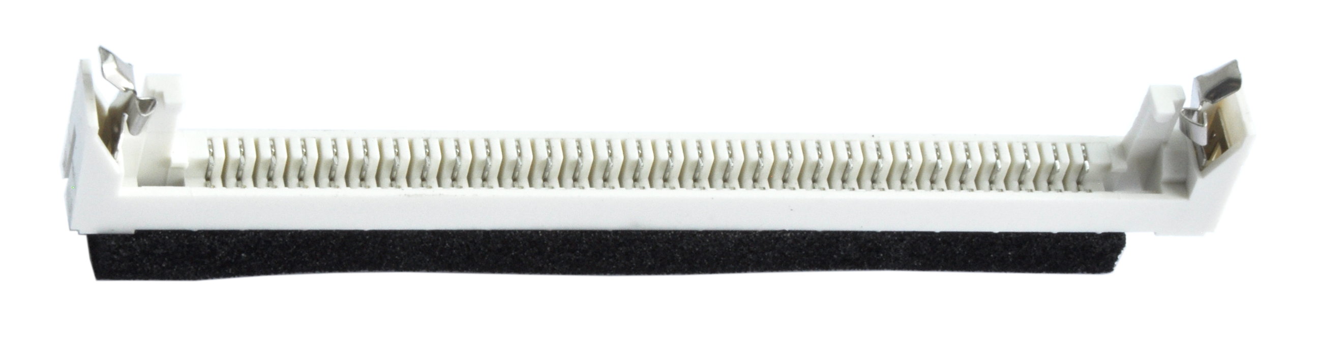
SIMM socket with protective foam removed, showing the SIPP-compatible pins

There is not a huge amount of grab in the socket as the pins aren't terribly long, but once everything is secure it does take a little force to remove again. The SIMM socket may come loose if SIMMs are removed, so probably best to remove the SIMM socket from the machine before replacing the SIMM memory stick itself.

SIPP sockets don't have any sort of mechanical keying, so make sure you insert the SIMM socket the right way! If you place a SIMM into the SIMM socket, one end of the SIMM has a groove cut into it. This groove is next to pin 1, and should line up with pin 1 of the SIPP socket, which should be labelled on the board (or possibly the opposite end is labelled with "30".)

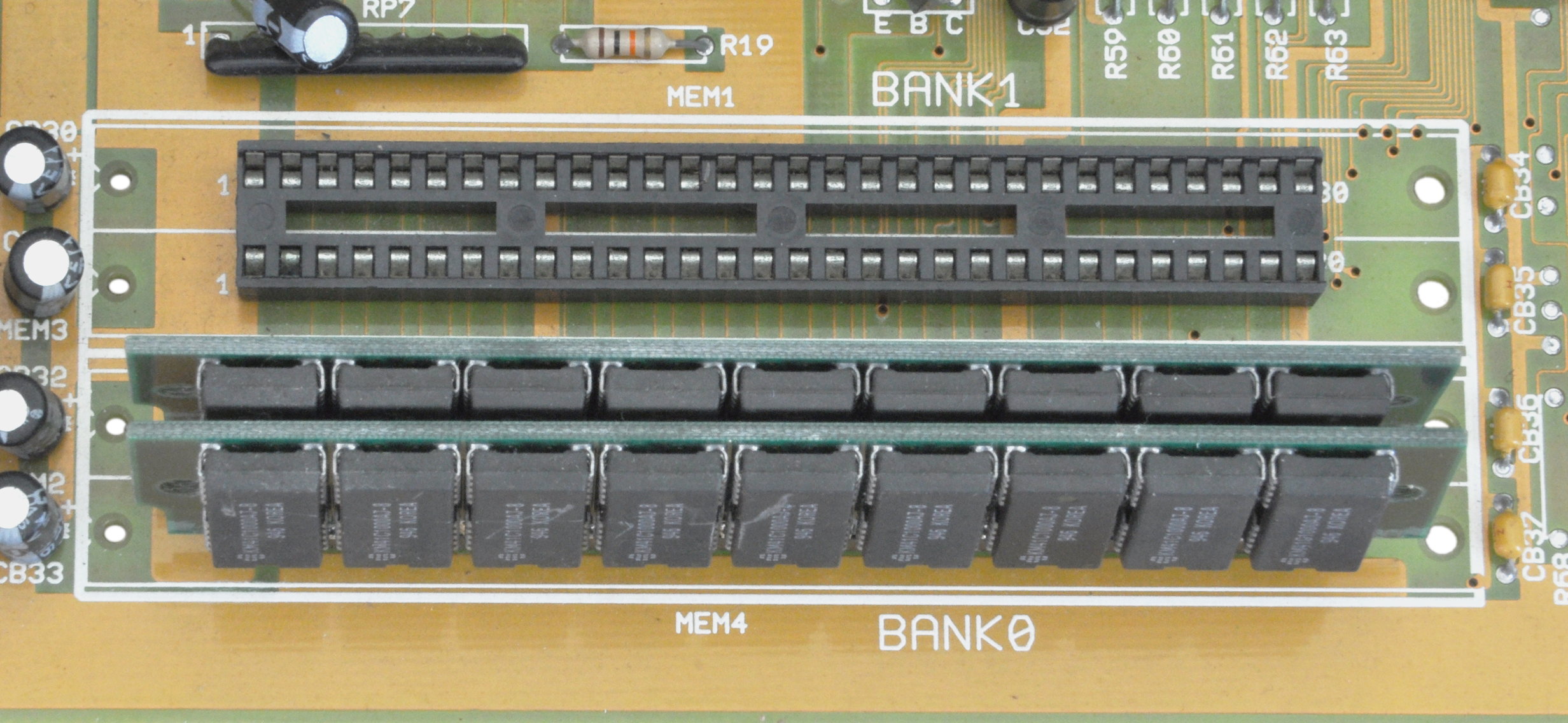
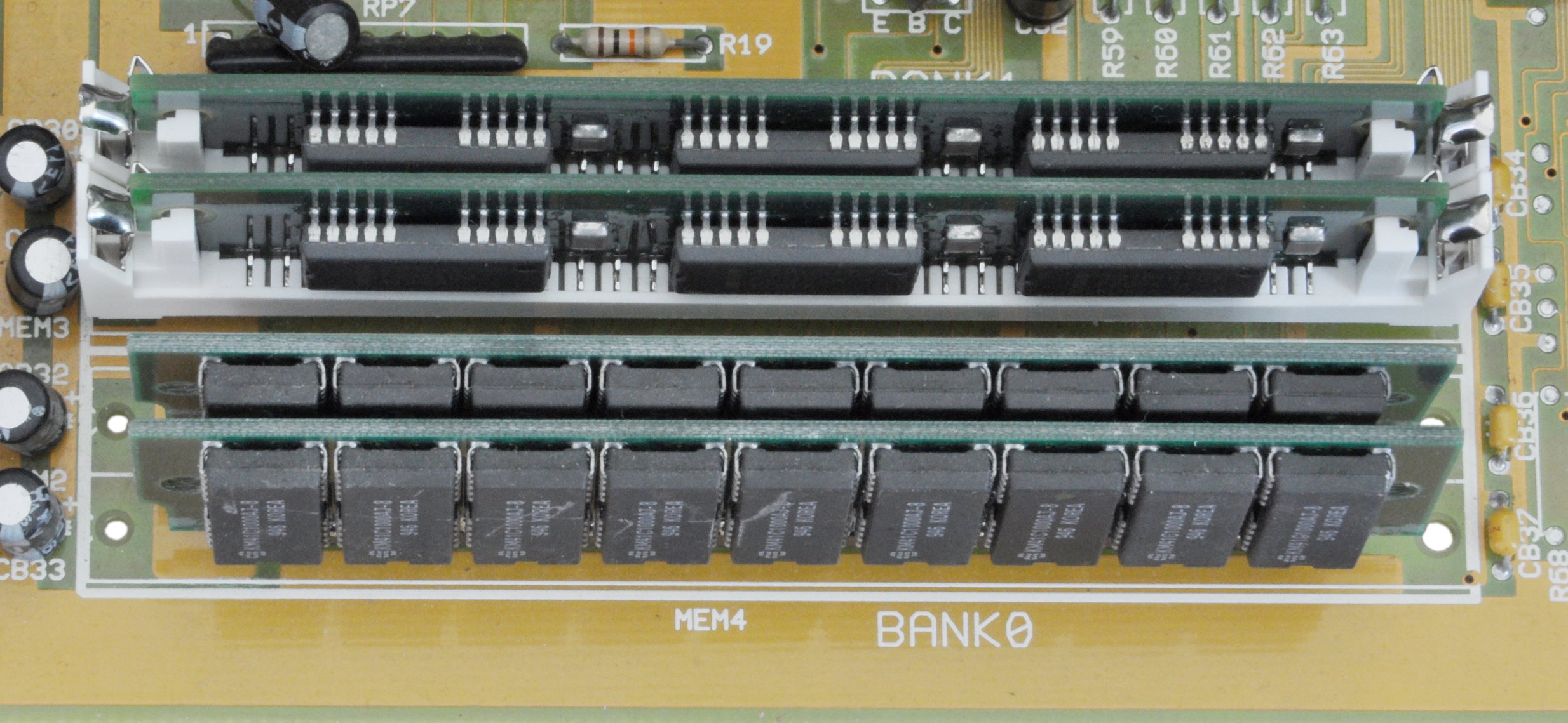
Two SIMMs installed in SIPP sockets.

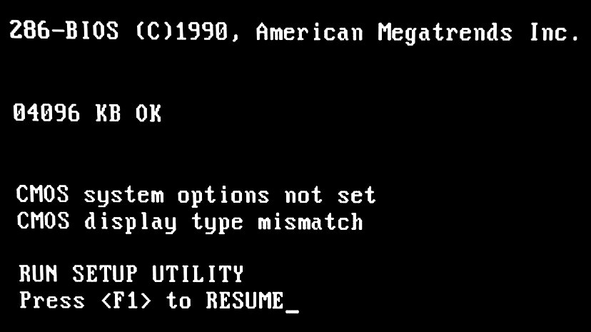
Otherwise, the solution works well, and my 286 correctly picks up the extra 2MB of memory added via the SIMM adapter.

4MB detected

At long last, I have maxed out the amount of memory on my 286 motherboard! (Although the 286 can address up to 16MB, this board only supports 4MB.)

2015-12-13

Renaissance CDFM music

Back in 1992, a group called Renaissance released a little demo called Amnesia. This demo would ultimately become one of the classics, known by all in the demoscene for its mesmerising visuals and stunning soundtrack.

The group would go on to release more demos, and eventually have a game published through Epic Megagames called Zone 66. Many of these demos, and indeed Zone 66, would use the same music system as originally demonstrated in Amnesia.

This music system was unique, in that it combined both digital sound (like the .mod format) with FM synthesis (like .mid/.cmf/.imf). The idea was that this would allow many more notes to be played at the same time, with a minimal impact on game speed thanks to the FM channels being mixed in hardware.

Zone 66 intro

Zone 66 was one of the first "next-generation" games I had the privilege of discovering, once I ventured beyond an 80286 and into the world of protected-mode games. The music captivated me, and I found Zone 66's intro sequence haunting. For years I dreamed of learning more about what format the music was and how it was played.

Eventually I found my way online, and to my dismay there was precious little about the Zone 66 music online. I discovered Amnesia, and that there had been such demand for its music that Renaissance had released a music player solely for Amnesia, but alas nothing for my beloved Zone 66 music. For a number of years, this was all there was.

In late 2009 I started working on Camoto - a suite of programs to extract, examine and modify DOS games. As I was always fond of music from DOS games, naturally one of the Camoto parts was dedicated to game music. Having implemented a number of completely different music file formats, I found I was beginning to get a feel for how people were storing music in their games. I decided to take another look at the Zone 66 music files, but I discovered that like the rest of the Zone 66 data files, they were compressed, so not knowing the compression algorithm (or much about how compression worked), my attempts at deciphering this enigma were met with very limited success.

I had been posting about the Zone 66 data files on the Xentax forums, sharing my progress and asking whether anyone had any insight into the compression algorithm that was being used. An individual by the name of John_Doe had a look at my notes and was able to take the next step, and completely understand the compression algorithm. This was the breakthrough I had been looking for! We were now able to decompress Zone 66's data files. While John_Doe was interested in the game levels, I headed straight for the music files.

These turned out to be far less complex than I expected. Certainly compared to the nightmare that was The Bone Shaker Architect, CDFM was a breath of fresh air. I could identify what looked like pattern data and what was very obviously instrument data, both FM and PCM. However I could not compress the Zone 66 data files, so I had no way of getting the game to play modified music. This is crucial for reverse-engineering, because the quickest way to work out a music file format is to change something at random, play the song, then listen for what has changed. After doing this a few dozen times you can start to work out which bytes control the pitch, which ones control the instruments, and so on.

At this point I remembered the Amnesia Music Player. Looking through the Amnesia data files, I found the uncompressed CDFM songs. I tried overwriting the first song's data with one of the decompressed Zone 66 music files, and much to my delight, the Amnesia Music Player started playing Zone 66 music instead. This meant I had a way to play modified songs, allowing reverse-engineering to proceed.

After many hours of tweaking data in a hex editor and listening to the opening bars of the Zone 66 intro tune so many times I was beginning to change my opinion of the music, I had finally deciphered the file format. There were four digital tracks and nine FM tracks. Instrument 1 was the first digital or FM instrument, depending on which track the event was played in. There weren't any effects, just note on/off and channel volume adjustment.

After documenting the format on the ModdingWiki, I set to work adding playback support to Camoto. The first time I heard the Zone 66 music being played through my own program was indescribable. After all these years pondering about this mysterious file format, I had finally discovered its secrets and had the only music player in the world outside of Renaissance themselves. Since Camoto could write S3M files with both FM and PCM instruments, I converted the songs to S3M format and posted them online to show the world the CDFM format was a mystery no more.

In my early searches for more information about CDFM, I stumbled across a page from 1994 by Trixter talking about this "CDFM" format that Renaissance were using. I sent Trixter an e-mail to let him know I had figured out the file format, and much to my surprise, he forwarded it to Daredevil, from Renaissance. I nearly fell off my chair when he replied with a copy of the original CDFM tracker, complete with source code!

I hastily ran it and had another surreal experience when I became one of a very select few who were seeing the original unreleased program used to compose the Amnesia and Zone 66 music. It might not seem like much to those outside the "scene", but for me it was mind-blowing to finally see this program after wondering about it for so long. I had assumed it was lost forever, like so much from this era.

Daredevil said that although it is quite rough and unfinished, he is happy for it to be made public, so I present here the Renaissance CDFM Tracker. Personally I find this work-in-progress view much more interesting, as it provides more of a behind-the-scenes look into how the program was used during game/demo development.

Download: cdfm.zip (3MB)

The download includes all CDFM tracks including some unreleased songs, as well as a couple of utilities. The tracker is designed for use with a Sound Blaster Pro 2 only, with fixed I/O, IRQ and DMA lines, so you will likely need to modify your DOSBox configuration file to get any sound out of the tracker. It works for me with the default SB16 settings, however these are the dosbox.conf settings recommended by Daredevil:

[sblaster]
sbtype=sbpro2
sbbase=220
irq=5
dma=1
hdma=5
sbmixer=true
oplmode=auto

The other options can be left as-is.

To launch the tracker, use the D.BAT helper, like this:

DIR MUSIC /W       ; List available music files
D ZONE0D           ; Choose a name from the list - no path, no extension

Once the player has loaded, press F5 to start playback. You may wish to press Tab once first, to switch from mono (default) to stereo mode. If you are missing FM instruments, try quitting the player (Alt + X) and rerunning it. You can press ? for help.

Here are some comments from Daredevil:

Some files worth noting:
  • 1.C - a small C program to recalculate the frequency table for 44100hz sample rate. You can probably ignore this but I thought it was cool :)
  • MPS.BAT - if you want to recompile CDFMSB, use this.
  • 670TOC67 - this will convert 670 files into C67 files that can be loaded into the composer. At the bottom of 670TOC67.C you will find some comments that document the file format of both of these.
  • MUSIC - these are all of the CDFM music files that I have. I wonder if Kenny or Ray have others? Not sure, but some were native C67 files and others I converted from 670. I'm pretty sure a few of them were not used in public releases but may have found their way out there in one form or another.
  • PLAY670.EXE - standalone 670 music player. I'm not sure where the source code is but it does seem to work in DOSBOX.

Kenny Chow later responded to say he doesn't have any of the original files any longer.

I still can't get over the fact that the CDFM tracker is now at long last public - and with source code too, no less. I hope those of you who are likewise fans of the Zone 66, Amnesia and other CDFM music are able to share in this amazing event!

Big thanks to Trixter for putting me in touch with Daredevil, and of course to Daredevil himself for having kept all this for so long, and being so willing to share it!

2015-11-29

Retrofitting a new EEPROM into an old PC

Recently I had the need to install an option ROM into my newly repaired 286, so that it could boot from IDE devices. That journey wasn't quite as straightforward as I had expected, so I thought I would write down what I'd done in case anyone else has a similar issue one day.

The fine folks at the XTIDE project have produced code suitable for use as an option ROM, which means if you can get it to appear in the PC's address space between C0000 and F0000 then the system BIOS will run the code automatically during the boot process, thus allowing booting from any installed IDE controller cards.

The easy option would have been to purchase a Lo-tech ISA ROM board, which allows a brand new EEPROM-compatible flash chip to appear in the correct address space. However I have many ISA network cards with boot ROM sockets, and since I intend to have a network card in each of these PCs anyway, I could save an expansion slot by putting the XTIDE ROM on the network card instead.

The complication arises as soon as you realise that almost all boot ROM sockets are 28-pin, and almost all 28-pin chips are older style EEPROMs, which require 12V to program and in many cases UV to erase. Since I don't have the hardware for this, my idea of reusing an old 28-pin chip was a dead end. I had previously used a PCI Realtek 8139 to dump 28-pin ROM chips, and this explains why it didn't seem to be capable of writing to them as well.

It turns out that most EEPROMs are standard 32-pin devices, and you can still buy them new for a few dollars each. Looking closely at the datasheets, I thought it might be possible to fit a 32-pin EEPROM into a 28-pin socket, if a few additional connections were made. With this plan in mind, I went ahead and purchased a handful of the same SST39SF020A chips used by the Lo-tech board, as well as some 32-pin EEPROM sockets to base my adapter on.

As it turns out, the adapter is very simple. You only need to connect all the overhanging pins together, and tie them to VCC (pin 28 on the 28-pin version.) One of these pins is the write enable line, so this means it is not possible to flash the chip in a 28-pin socket. It also means if you modify the chip directly, it will no longer be possible to reflash it. By modifying a 32-pin IC socket instead, the chip can be removed and reflashed as needed in a native 32-pin programmer.

This is the pinout of the two chip types:

From here you can see that if we plugged the 32-pin chip into the 28-pin socket, with pins 1-2 and 31-32 overhanging the socket, all the data lines and most of the address lines match up. However VCC would arrive on pin 30 and the real VCC pin would be without power. To build an adapter we will need to at least connect power to the real VCC. Pin 31 also enables write mode when pulled low, so we can tie that to VCC as well to ensure the chip is always in read-mode.

Since pin 30 (where VCC is coming in from the 28-pin socket) is used for A17, and A17 is only needed to access storage capacity larger than 128kB, we can leave that connected to VCC for simplicity. The drawback of doing this is that we will "limit" our storage capacity to 128kB, however this is not really a limit, because the 28-pin socket does not have an A17 line so it can only access a maximum of 128kB anyway.

The A16 and NC (pin 1, used for A18 in 512kB chips) should also be tied to something, so we will use VCC as well since it is close by. If we didn't do this and left the pins unconnected, they will "float" and could change value unexpectedly. This would effectively make the contents of the ROM vanish momentarily, causing the PC to lock up if it happened to be running code from the chip at the time.

EEPROM memory map. Only the upper 128kB will be visible through the 28-pin socket, whatever the chip capacity.
The net effect of all this is that all the upper address lines will always be high, causing only the upper 128kB of flash storage to be accessible. This is important when flashing the chip, as any chip larger than 128kB will need the desired content placed in the highest 128kB. If a 512kB chip is used for example, then data from 0kB to 384kB will be ignored, and only the 128kB window from 384kB to 512kB will be accessible through the 28-pin socket. Anything reading the 28-pin socket will of course be none-the-wiser, and will access the data from 0kB to 128kB as normal.

Connecting all these pins together looks like this: (connections shown in red)

As mentioned previously, making these connections directly to a chip will prevent it from being reflashed, so for maximum flexibility a 32-pin PDIP socket should be modified so the flash chip can be removed as needed. The 32-pin PDIP socket fits nicely into a 28-pin socket, which means the only parts required to construct this adapter are the 32-pin socket itself and some very short lengths of wire.

After making the necessary connections, the adapter should look like this:

This picture is of course looking from the bottom up, so the connections are mirrored compared to the top-down view shown in the earlier diagrams. This adapter mounts nicely in a 28-pin EEPROM socket:

It also doesn't stick out much farther than normal, so it just fits in the available slot space without interfering with the neighbouring slot.

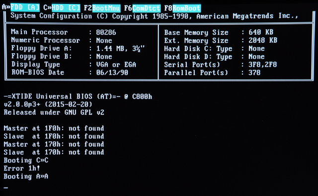
In my case, after having flashed the XTIDE BIOS, the 286 recognised the option ROM on the first attempt and happily ran it during the boot process!

Flashing the chip

To actually flash the chip, I used the fine flashrom tool.

Unfortunately my first attempt was to use a 3Com 3C905 Ethernet card as it was the only one I had with a 32-pin EEPROM socket, however I discovered that this card lacks the A17 address line, restricting its ability to flashing chips that are 128kB or smaller. Since I had a 256kB chip, and the 28-pin adapter requires the content placed in the upper-most address, I couldn't put the XTIDE code in the upper 128kB if the 3Com card could only flash the lower 128kB of the chip!

I then noticed the motherboard I was using - a Gigabyte GA-6BXC - had a 32-pin BIOS chip. Flashrom supports the Intel PIIX4 chipset used by this motherboard, so I could hot-flash the chip using the motherboard's BIOS socket.

I had never hot-flashed a machine before, but the process was very simple. Once Linux had started booting, the motherboard BIOS chip was removed, and the target EEPROM carefully placed in the socket. I didn't push it all the way in, just enough to make contact. Flashrom detected the chip, wrote the content and verified it again without complaint, so I could be sure the content was flashed successfully and the chip was easy to remove again. Since I had to buy the flash chips in a pack of 5, I used the hot-flash process to flash all five chips. One of them was bad - flashrom couldn't recognise it and the chip got very hot very quickly, but the other four were fine (and yes I tried three times and the chip was definitely in the right way.)

Since the XTIDE BIOS is only 8kB (or 12kB for the "large" version), it needs to be padded up to the size of the flash chip - 256kB in my case. I used a simple shell script for this:

$ (for ((I=12288; $I<16384; I=$[$I+1])); do echo -en "\xFF"; done) > pad.bin
$ cat ide_atl.bin pad.bin > xtide-16k.bin
$ cat xtide-16k.bin xtide-16k.bin xtide-16k.bin xtide-16k.bin > xtide-64k.bin
$ cat xtide-64k.bin xtide-64k.bin xtide-64k.bin xtide-64k.bin > xtide-256k.bin

This creates a 256kB file, with the complete XTIDE ROM at every 16kB mark. This means we only need to tell the Ethernet card the boot ROM is 16kB in size, and it won't need to take up a huge amount of memory which could otherwise be used for UMBs. Technically we could have done the calculations to get the XTIDE code to sit at exactly the 128kB mark, but since the rest of the chip is going to be ignored, it doesn't matter if we have duplicate data in there anyway.

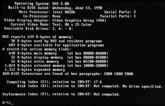
I flashed this 256kB file to the chip and placed it in the network card's boot ROM socket, and to my surprise everything worked the first time. You can see in the output of Norton Utilities' SI that there is an option ROM at address C800 (along with the video BIOS at C000 and the system BIOS at F000):

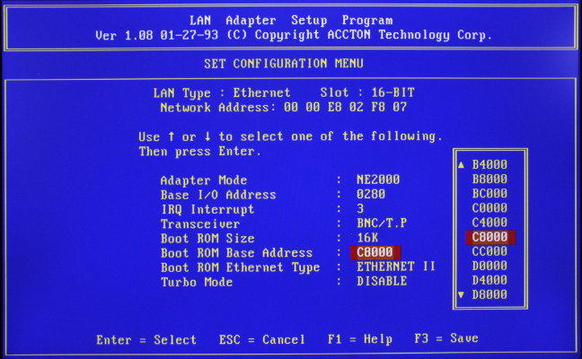
Part of the reason for the early success was because I had already found the configuration program for my network card and enabled the boot ROM socket, which was disabled by default. Finding the program to do this was a bit of a challenge, and I'm considering starting a wiki-like card database to assist with this issue.

In my case (and to help anyone from Google), the card had an EN50903 chipset, with "A.T.C." on it (which stands for Accton Technology Corporation.) It turns out the EN50903 is used on a few cards, but mine was an Accton EN1640. Googling for en1640.zip got me the DOS drivers with the setup program, allowing me to set the port address, IRQ, and enable the boot ROM. Since my VGA BIOS stopped at segment C800, I put the boot ROM there and set it to 16kB. (Side note: it turns out the EN50903 is happy running in 8-bit mode, so this solution should also work for an XT, even though the card has a 16-bit ISA connector.)

Now I can start using IDE devices with my 286!

2015-06-07

Converting a CVS repository to git

With the recent loss of trust in SourceForge as a reputable open-source hosting platform, I decided to see how difficult it would be to move the CVS repository for AdPlug off SourceForge, and over to GitHub. As it turned out, the process is relatively straightforward once you work out what needs to be done.

For this process I used cvs2git, which is part of the cvs2svn project. There are a handful of other alternative tools available, but this one seems to be the most recommended.