I recently obtained a faulty LTO5 tape drive with a sticky head. I was able to successfully repair it by just giving it a good clean, and the drive is now fully functional again. To help anyone who might come across the same problem in the future, I took some photos of the process. Although this was an LTO5 drive, the procedure is likely to be very similar for other generations of LTO drives as well. However this was a HP drive, so the procedure will likely only apply to other drives manufactured by HP.
Symptoms
When inserting a tape, the drive normally makes one or two knocking noises. This is the drive making sure the head can move through its full range of motion. This particular drive was making a number of knocking sounds (around 10) and then immediately ejecting the tape. Running HP Tape Tools diagnostics on the drive reported that the drive "may have problems loading a tape" and the Drive Assessment Test failed early with an error about the head not moving the expected distance.
Inserting a cleaning tape resulted in the drive winding it in quite some distance and then rebooting (all LEDs light up). The drive then went into 'power on with tape loaded' mode, very slowly rewinding the tape over many minutes and then ejecting it. The drive logs reported the drive being power cycled while a tape was loaded, even though power was not lost to the drive. Apparently there is a bug in the firmware and inserting a cleaning tape when the head cannot move properly causes the firmware to crash and reboot.
Disassembling the drive and gently moving the head with a pair of tweezers showed that the head did not move freely and there was some very slight friction at two points along its journey. Inserting a tape with the drive's cover removed (so the head was visible) revealed that the head could not lift all the way up under its own power, and the repeated knocking sound was the head trying a number of times to unsuccessfully move. Using tweezers to assist the head resulted in the drive loading a tape, and the head appeared to move perfectly fine after this point. However HP Tape Tools revealed high error rates (poor write speeds) and the drive had problems finding the start of the tape.
Solution
After disassembling the drive, it turned out that there was a tiny build up of some gunk (dust?) on the shaft that the head slides up and down on. There is no way to get access to clean this shaft unless the whole head assembly is removed from the drive and disassembled, however this is actually a relatively straightforward task, and isn't overly fiddly. With only a little care, the drive heads remain aligned so the risk of damaging the drive is minimal. (Of course the old saying applies: YMMV, do this at your own risk, etc, etc.)
Drive disassembly
To disassemble the drive you will need a T8 torx bit to remove the screws on the top of the drive, and a T4 torx bit to disassemble the head itself. You'll also need a pair of needle-nose pliers or similar in order to undo two nuts to release the head assembly.
First remove the four screws that hold the top of the drive's metal case, and cut the various stickers. Lift the top off gently so the thermal pads aren't damaged.
Once the lid is off, the main PCB is exposed. This needs to be completely disconnected. Remove all the cables connecting to this board, as shown in the images below.
The flat ribbon cables need to be released differently. The ribbon cables with a blue end are released by lifting up the black part of the socket from the back, while the other cable is released by lifting up the black part from the front. I used tweezers to gently lift it. The following two photos show the two variants of the connectors before and after release.
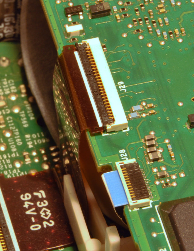
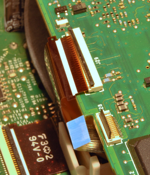
Disconnect all the cables on the board.
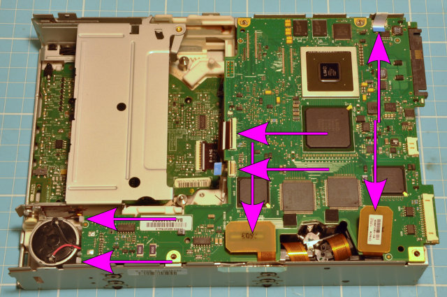
The board must be lifted up slightly (and wiggled out of the way of the white plastic clips) in order to access the last two connectors. The flat ribbon cable is gently pulled out, while the white connector for the ejection motor requires a little more force, but be careful not to damage the connector. Wiggle it quite a bit as you are pulling it to release it.
Once the main PCB has been removed, locate the head assembly towards the rear of the drive. There are two shafts that secure the head assembly into the drive, and both of them have a spring and a nut on them so are easily identified. Unscrew the nut and remove the spring. This releases the head assembly but do not lift it out yet as more cables need to be detached first.
Be careful to leave the other grub screws untouched in the corners of the head assembly base, as these are used to align the head. If they are moved then the head will not read or write data at the correct angle and the drive will need to be professionally recalibrated before it will work again.
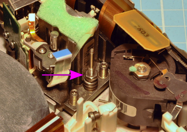
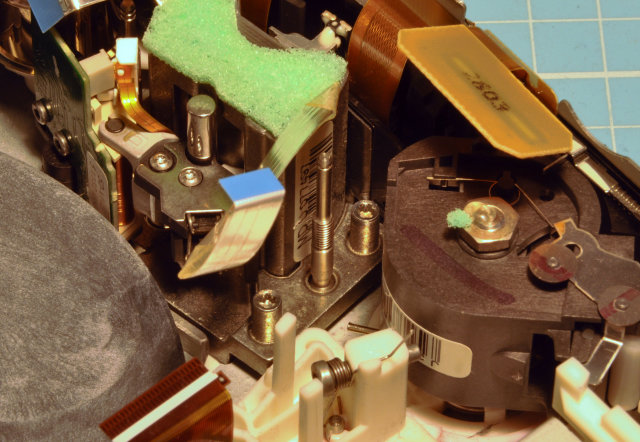
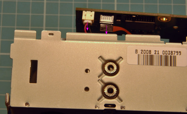
Now the data cables for the head itself need to be removed. On the side of the drive there is a hole with a black plastic catch sitting in it. Poke this in a little to release the plastic bracket holding the data cable in place, which can then be lifted up completely clear of the drive.
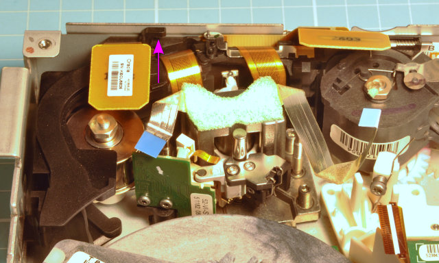
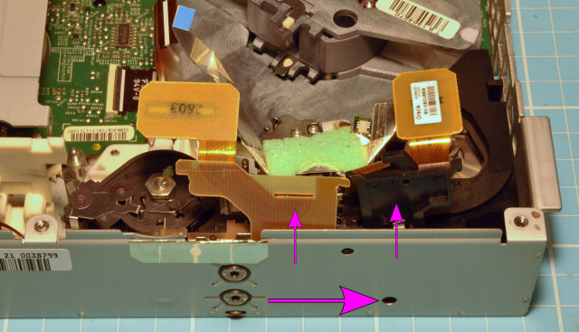
Once the head's data cables are free, the head assembly can be completely lifted out of the drive. Be careful not to touch the head itself.
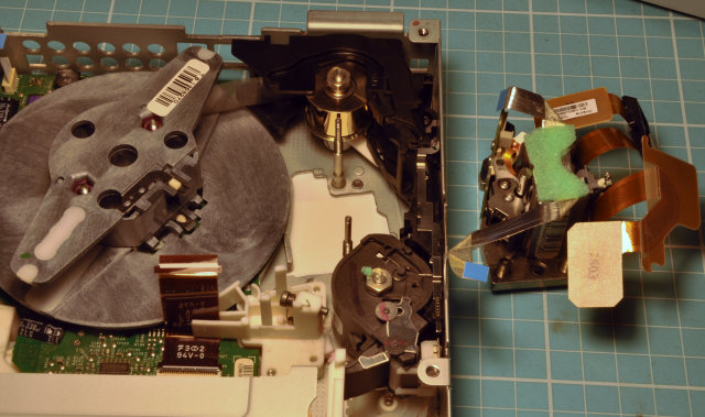
Set the drive aside as we are now focusing on just the head assembly. The whole thing needs to be disassembled and it comes apart into five pieces: the base, the head, the housing and two small metal cylinders.
First, turn the assembly upside down and undo the two screws that hold the housing in place. Leave the third screw in place.

Next, pull the housing away from the base, if possible leaving the head on the base. If the head comes off it's fine, it can just become stuck if it moves around too freely during the procedure. Note that the head is attached to the base by a thin ribbon cable with a white connector. This will need to be removed at some point before the head is lifted off the base, however the housing sometimes gets in the way. Try to remove it if you can, otherwise be sure that the head does not lift off the base when you remove the housing.
There are strong magnets in the housing, so it will require some force to move and you may need to lever it at first with a screwdriver or similar. Be very careful not to damage the head itself during this process.
As you lift the housing off, two small metal cylinders will fall out and stick to the magnets. Just ignore these, but at this point you cannot go back as the cylinders now prevent the housing from being pushed back in place.
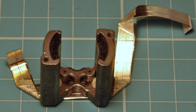
I drew a black dot on one side of the cylinders so I could be sure I was inserting them back in the same way later, but they turned out not to be magnetic so this may not matter. However you may like me wish to err on the side of caution! You will need pliers or similar to remove the cylinders as the magnets they are stuck against are quite strong. Set the cylinders aside as they are placed back in the housing later after reassembly, from the top instead.
The head can now be lifted out of the base if it did not come out already, after carefully disconnecting the thin cable if you haven't already.


Simply rubbing the surfaces with a dry cotton bud did the job in my case, however when running it along the thick shaft on the base of the head assembly (see arrow in previous pic) there was noticeable friction in exactly the same pattern as the head exhibited earlier. Scrubbing this until it was mostly smooth did the trick, as reassembling the head immediately revealed that there was no further friction and the head could slide smoothly along the shaft once again.
To put the head assembly back together, place the head onto the base and gently push the housing over the top, leaving the two small metal cylinders aside for later. Be sure the housing fits snugly and there are no gaps between the housing and the base, as this is easy to have happen because of the strong magnets. Screw the housing back to the base and confirm that the head still slides smoothly. Don't forget to reconnect the small ribbon cable with the white connector.
Peel the cable and sponge off the top of the head housing to reveal the holes where the cylinders go. Pop both cylinders back in and press down the cable and sponge again.
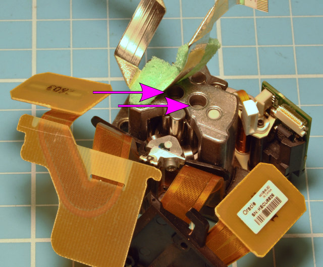
Follow the rest of the disassembly instructions in reverse, remembering to connect all the cables on the PCB before switching the drive back on again.
Hopefully you have the same success that I did!
Excellent post! I found myself in a similar situation with an LTO4 drive that looks nearly identical inside (Tandberg, but uses HP software), except I was opening it attempt to deep clean the head rather than free it (drive was writing about 75% capacity at nerfed speed, cleaning tapes didnt help).
ReplyDeleteUnfortunately I got unlucky and assumed the opposite from this post, i.e. that the 4 outer screws held the head in and the 2 long shafts were part of the head assembly, so I ended up screwing the alignment. I tried a few times to 'guess' the correct torque, but ended up causing so much fatigue in the head ribbon from inserting and removing the PCB each time that it tore. Which brings me to the main purpose of this comment - be careful with head ribbons if attempting this, they are insanely fragile compared to the average ribbon cable.
Thanks for the detailed review. I was looking for disassembly of this device for a long time.
ReplyDeleteI want to ask you for help.
Can you take a picture or schematically indicate how the carrier is located? Our cartridge lost leader pin and the carrier apeared on bobbin.
Your picture (Head assembly removed from drive) shows that the carrier's head is near insert window.
This comment has been removed by the author.
ReplyDeletenever mind - i found the way to get head like on mentioned picture by placing a clean cartridge and spinning the gear (for manual release) to unlock the way.
ReplyDelete