2015-12-13

Renaissance CDFM music

Back in 1992, a group called Renaissance released a little demo called Amnesia. This demo would ultimately become one of the classics, known by all in the demoscene for its mesmerising visuals and stunning soundtrack.

The group would go on to release more demos, and eventually have a game published through Epic Megagames called Zone 66. Many of these demos, and indeed Zone 66, would use the same music system as originally demonstrated in Amnesia.

This music system was unique, in that it combined both digital sound (like the .mod format) with FM synthesis (like .mid/.cmf/.imf). The idea was that this would allow many more notes to be played at the same time, with a minimal impact on game speed thanks to the FM channels being mixed in hardware.

Zone 66 intro

Zone 66 was one of the first "next-generation" games I had the privilege of discovering, once I ventured beyond an 80286 and into the world of protected-mode games. The music captivated me, and I found Zone 66's intro sequence haunting. For years I dreamed of learning more about what format the music was and how it was played.

Eventually I found my way online, and to my dismay there was precious little about the Zone 66 music online. I discovered Amnesia, and that there had been such demand for its music that Renaissance had released a music player solely for Amnesia, but alas nothing for my beloved Zone 66 music. For a number of years, this was all there was.

In late 2009 I started working on Camoto - a suite of programs to extract, examine and modify DOS games. As I was always fond of music from DOS games, naturally one of the Camoto parts was dedicated to game music. Having implemented a number of completely different music file formats, I found I was beginning to get a feel for how people were storing music in their games. I decided to take another look at the Zone 66 music files, but I discovered that like the rest of the Zone 66 data files, they were compressed, so not knowing the compression algorithm (or much about how compression worked), my attempts at deciphering this enigma were met with very limited success.

I had been posting about the Zone 66 data files on the Xentax forums, sharing my progress and asking whether anyone had any insight into the compression algorithm that was being used. An individual by the name of John_Doe had a look at my notes and was able to take the next step, and completely understand the compression algorithm. This was the breakthrough I had been looking for! We were now able to decompress Zone 66's data files. While John_Doe was interested in the game levels, I headed straight for the music files.

These turned out to be far less complex than I expected. Certainly compared to the nightmare that was The Bone Shaker Architect, CDFM was a breath of fresh air. I could identify what looked like pattern data and what was very obviously instrument data, both FM and PCM. However I could not compress the Zone 66 data files, so I had no way of getting the game to play modified music. This is crucial for reverse-engineering, because the quickest way to work out a music file format is to change something at random, play the song, then listen for what has changed. After doing this a few dozen times you can start to work out which bytes control the pitch, which ones control the instruments, and so on.

At this point I remembered the Amnesia Music Player. Looking through the Amnesia data files, I found the uncompressed CDFM songs. I tried overwriting the first song's data with one of the decompressed Zone 66 music files, and much to my delight, the Amnesia Music Player started playing Zone 66 music instead. This meant I had a way to play modified songs, allowing reverse-engineering to proceed.

After many hours of tweaking data in a hex editor and listening to the opening bars of the Zone 66 intro tune so many times I was beginning to change my opinion of the music, I had finally deciphered the file format. There were four digital tracks and nine FM tracks. Instrument 1 was the first digital or FM instrument, depending on which track the event was played in. There weren't any effects, just note on/off and channel volume adjustment.

After documenting the format on the ModdingWiki, I set to work adding playback support to Camoto. The first time I heard the Zone 66 music being played through my own program was indescribable. After all these years pondering about this mysterious file format, I had finally discovered its secrets and had the only music player in the world outside of Renaissance themselves. Since Camoto could write S3M files with both FM and PCM instruments, I converted the songs to S3M format and posted them online to show the world the CDFM format was a mystery no more.

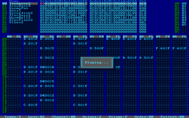
In my early searches for more information about CDFM, I stumbled across a page from 1994 by Trixter talking about this "CDFM" format that Renaissance were using. I sent Trixter an e-mail to let him know I had figured out the file format, and much to my surprise, he forwarded it to Daredevil, from Renaissance. I nearly fell off my chair when he replied with a copy of the original CDFM tracker, complete with source code!

I hastily ran it and had another surreal experience when I became one of a very select few who were seeing the original unreleased program used to compose the Amnesia and Zone 66 music. It might not seem like much to those outside the "scene", but for me it was mind-blowing to finally see this program after wondering about it for so long. I had assumed it was lost forever, like so much from this era.

Daredevil said that although it is quite rough and unfinished, he is happy for it to be made public, so I present here the Renaissance CDFM Tracker. Personally I find this work-in-progress view much more interesting, as it provides more of a behind-the-scenes look into how the program was used during game/demo development.

Download: cdfm.zip (3MB)

The download includes all CDFM tracks including some unreleased songs, as well as a couple of utilities. The tracker is designed for use with a Sound Blaster Pro 2 only, with fixed I/O, IRQ and DMA lines, so you will likely need to modify your DOSBox configuration file to get any sound out of the tracker. It works for me with the default SB16 settings, however these are the dosbox.conf settings recommended by Daredevil:

[sblaster]
sbtype=sbpro2
sbbase=220
irq=5
dma=1
hdma=5
sbmixer=true
oplmode=auto

The other options can be left as-is.

To launch the tracker, use the D.BAT helper, like this:

DIR MUSIC /W       ; List available music files
D ZONE0D           ; Choose a name from the list - no path, no extension

Once the player has loaded, press F5 to start playback. You may wish to press Tab once first, to switch from mono (default) to stereo mode. If you are missing FM instruments, try quitting the player (Alt + X) and rerunning it. You can press ? for help.

Here are some comments from Daredevil:

Some files worth noting:
  • 1.C - a small C program to recalculate the frequency table for 44100hz sample rate. You can probably ignore this but I thought it was cool :)
  • MPS.BAT - if you want to recompile CDFMSB, use this.
  • 670TOC67 - this will convert 670 files into C67 files that can be loaded into the composer. At the bottom of 670TOC67.C you will find some comments that document the file format of both of these.
  • MUSIC - these are all of the CDFM music files that I have. I wonder if Kenny or Ray have others? Not sure, but some were native C67 files and others I converted from 670. I'm pretty sure a few of them were not used in public releases but may have found their way out there in one form or another.
  • PLAY670.EXE - standalone 670 music player. I'm not sure where the source code is but it does seem to work in DOSBOX.

Kenny Chow later responded to say he doesn't have any of the original files any longer.

I still can't get over the fact that the CDFM tracker is now at long last public - and with source code too, no less. I hope those of you who are likewise fans of the Zone 66, Amnesia and other CDFM music are able to share in this amazing event!

Big thanks to Trixter for putting me in touch with Daredevil, and of course to Daredevil himself for having kept all this for so long, and being so willing to share it!

2015-11-29

Retrofitting a new EEPROM into an old PC

Recently I had the need to install an option ROM into my newly repaired 286, so that it could boot from IDE devices. That journey wasn't quite as straightforward as I had expected, so I thought I would write down what I'd done in case anyone else has a similar issue one day.

The fine folks at the XTIDE project have produced code suitable for use as an option ROM, which means if you can get it to appear in the PC's address space between C0000 and F0000 then the system BIOS will run the code automatically during the boot process, thus allowing booting from any installed IDE controller cards.

The easy option would have been to purchase a Lo-tech ISA ROM board, which allows a brand new EEPROM-compatible flash chip to appear in the correct address space. However I have many ISA network cards with boot ROM sockets, and since I intend to have a network card in each of these PCs anyway, I could save an expansion slot by putting the XTIDE ROM on the network card instead.

The complication arises as soon as you realise that almost all boot ROM sockets are 28-pin, and almost all 28-pin chips are older style EEPROMs, which require 12V to program and in many cases UV to erase. Since I don't have the hardware for this, my idea of reusing an old 28-pin chip was a dead end. I had previously used a PCI Realtek 8139 to dump 28-pin ROM chips, and this explains why it didn't seem to be capable of writing to them as well.

It turns out that most EEPROMs are standard 32-pin devices, and you can still buy them new for a few dollars each. Looking closely at the datasheets, I thought it might be possible to fit a 32-pin EEPROM into a 28-pin socket, if a few additional connections were made. With this plan in mind, I went ahead and purchased a handful of the same SST39SF020A chips used by the Lo-tech board, as well as some 32-pin EEPROM sockets to base my adapter on.

As it turns out, the adapter is very simple. You only need to connect all the overhanging pins together, and tie them to VCC (pin 28 on the 28-pin version.) One of these pins is the write enable line, so this means it is not possible to flash the chip in a 28-pin socket. It also means if you modify the chip directly, it will no longer be possible to reflash it. By modifying a 32-pin IC socket instead, the chip can be removed and reflashed as needed in a native 32-pin programmer.

This is the pinout of the two chip types:

From here you can see that if we plugged the 32-pin chip into the 28-pin socket, with pins 1-2 and 31-32 overhanging the socket, all the data lines and most of the address lines match up. However VCC would arrive on pin 30 and the real VCC pin would be without power. To build an adapter we will need to at least connect power to the real VCC. Pin 31 also enables write mode when pulled low, so we can tie that to VCC as well to ensure the chip is always in read-mode.

Since pin 30 (where VCC is coming in from the 28-pin socket) is used for A17, and A17 is only needed to access storage capacity larger than 128kB, we can leave that connected to VCC for simplicity. The drawback of doing this is that we will "limit" our storage capacity to 128kB, however this is not really a limit, because the 28-pin socket does not have an A17 line so it can only access a maximum of 128kB anyway.

The A16 and NC (pin 1, used for A18 in 512kB chips) should also be tied to something, so we will use VCC as well since it is close by. If we didn't do this and left the pins unconnected, they will "float" and could change value unexpectedly. This would effectively make the contents of the ROM vanish momentarily, causing the PC to lock up if it happened to be running code from the chip at the time.

EEPROM memory map. Only the upper 128kB will be visible through the 28-pin socket, whatever the chip capacity.
The net effect of all this is that all the upper address lines will always be high, causing only the upper 128kB of flash storage to be accessible. This is important when flashing the chip, as any chip larger than 128kB will need the desired content placed in the highest 128kB. If a 512kB chip is used for example, then data from 0kB to 384kB will be ignored, and only the 128kB window from 384kB to 512kB will be accessible through the 28-pin socket. Anything reading the 28-pin socket will of course be none-the-wiser, and will access the data from 0kB to 128kB as normal.

Connecting all these pins together looks like this: (connections shown in red)

As mentioned previously, making these connections directly to a chip will prevent it from being reflashed, so for maximum flexibility a 32-pin PDIP socket should be modified so the flash chip can be removed as needed. The 32-pin PDIP socket fits nicely into a 28-pin socket, which means the only parts required to construct this adapter are the 32-pin socket itself and some very short lengths of wire.

After making the necessary connections, the adapter should look like this:

This picture is of course looking from the bottom up, so the connections are mirrored compared to the top-down view shown in the earlier diagrams. This adapter mounts nicely in a 28-pin EEPROM socket:

It also doesn't stick out much farther than normal, so it just fits in the available slot space without interfering with the neighbouring slot.

In my case, after having flashed the XTIDE BIOS, the 286 recognised the option ROM on the first attempt and happily ran it during the boot process!

Flashing the chip

To actually flash the chip, I used the fine flashrom tool.

Unfortunately my first attempt was to use a 3Com 3C905 Ethernet card as it was the only one I had with a 32-pin EEPROM socket, however I discovered that this card lacks the A17 address line, restricting its ability to flashing chips that are 128kB or smaller. Since I had a 256kB chip, and the 28-pin adapter requires the content placed in the upper-most address, I couldn't put the XTIDE code in the upper 128kB if the 3Com card could only flash the lower 128kB of the chip!

I then noticed the motherboard I was using - a Gigabyte GA-6BXC - had a 32-pin BIOS chip. Flashrom supports the Intel PIIX4 chipset used by this motherboard, so I could hot-flash the chip using the motherboard's BIOS socket.

I had never hot-flashed a machine before, but the process was very simple. Once Linux had started booting, the motherboard BIOS chip was removed, and the target EEPROM carefully placed in the socket. I didn't push it all the way in, just enough to make contact. Flashrom detected the chip, wrote the content and verified it again without complaint, so I could be sure the content was flashed successfully and the chip was easy to remove again. Since I had to buy the flash chips in a pack of 5, I used the hot-flash process to flash all five chips. One of them was bad - flashrom couldn't recognise it and the chip got very hot very quickly, but the other four were fine (and yes I tried three times and the chip was definitely in the right way.)

Since the XTIDE BIOS is only 8kB (or 12kB for the "large" version), it needs to be padded up to the size of the flash chip - 256kB in my case. I used a simple shell script for this:

$ (for ((I=12288; $I<16384; I=$[$I+1])); do echo -en "\xFF"; done) > pad.bin
$ cat ide_atl.bin pad.bin > xtide-16k.bin
$ cat xtide-16k.bin xtide-16k.bin xtide-16k.bin xtide-16k.bin > xtide-64k.bin
$ cat xtide-64k.bin xtide-64k.bin xtide-64k.bin xtide-64k.bin > xtide-256k.bin

This creates a 256kB file, with the complete XTIDE ROM at every 16kB mark. This means we only need to tell the Ethernet card the boot ROM is 16kB in size, and it won't need to take up a huge amount of memory which could otherwise be used for UMBs. Technically we could have done the calculations to get the XTIDE code to sit at exactly the 128kB mark, but since the rest of the chip is going to be ignored, it doesn't matter if we have duplicate data in there anyway.

I flashed this 256kB file to the chip and placed it in the network card's boot ROM socket, and to my surprise everything worked the first time. You can see in the output of Norton Utilities' SI that there is an option ROM at address C800 (along with the video BIOS at C000 and the system BIOS at F000):

Part of the reason for the early success was because I had already found the configuration program for my network card and enabled the boot ROM socket, which was disabled by default. Finding the program to do this was a bit of a challenge, and I'm considering starting a wiki-like card database to assist with this issue.

In my case (and to help anyone from Google), the card had an EN50903 chipset, with "A.T.C." on it (which stands for Accton Technology Corporation.) It turns out the EN50903 is used on a few cards, but mine was an Accton EN1640. Googling for en1640.zip got me the DOS drivers with the setup program, allowing me to set the port address, IRQ, and enable the boot ROM. Since my VGA BIOS stopped at segment C800, I put the boot ROM there and set it to 16kB. (Side note: it turns out the EN50903 is happy running in 8-bit mode, so this solution should also work for an XT, even though the card has a 16-bit ISA connector.)

Now I can start using IDE devices with my 286!

2015-06-07

Converting a CVS repository to git

With the recent loss of trust in SourceForge as a reputable open-source hosting platform, I decided to see how difficult it would be to move the CVS repository for AdPlug off SourceForge, and over to GitHub. As it turned out, the process is relatively straightforward once you work out what needs to be done.

For this process I used cvs2git, which is part of the cvs2svn project. There are a handful of other alternative tools available, but this one seems to be the most recommended.